Physical Structure
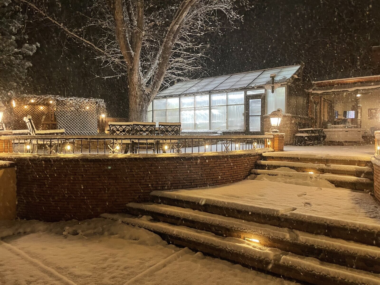
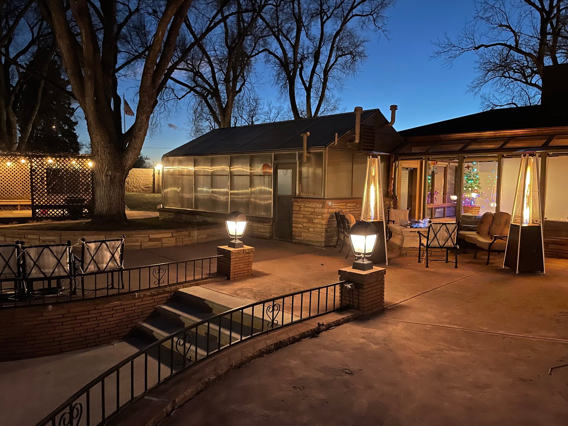
This is the detailed measurement and physics reference behind The Greenhouse. Start with the overview page for the human-scale tour, then use this page for dimensions, glazing, airflow, thermal envelope, and solar geometry. Live visual context is available on Greenhouse Cameras.
Dimensions & Shape
Interior dimensions below are direct tape measurements from April 2026, generally precise to ±0.5”. Orientation and elevation are supported by map/satellite measurements and are treated as canonical constants for solar-angle reasoning until a future survey replaces them.
Rectangular body with a three-face convex south end.
Constant east-west width across the full structure.
269" rectangular section plus a 70" deep south convex section.
Interior usable floor area for crop layout and equipment planning.
Interior air volume, including the tall peaked roof.
Floor to truss line before the roof rises to the ridge.
Floor to ridge beam top at the highest point.
Longmont elevation, important for air density and VPD behavior.
Long-axis orientation for solar-angle reasoning.
Measurement Model
To avoid mixing unlike measurements, this page distinguishes between:
-
Interior usable geometry — tape-measured floor dimensions used for crop area, equipment layout, and air volume
-
Exterior/remote geometry — map or satellite-derived measurements used for orientation, footprint context, and future sun-angle analysis Current canonical values:
-
Interior usable floor area: ~367 sq ft
-
Interior air volume: ~3,614 cu ft
-
Exterior footprint: likely larger than interior usable area and still subject to refinement
-
Long-axis heading: 156.49° for solar and orientation calculations
Floor Plan
Shared with the house. Interior door, mechanical systems, and 49" equipment shelf. This wall is thermal buffer and utility spine, not growing surface.
Longest uninterrupted growing surface. Six shelf bays, strong grow-light coverage, and late-day solar exposure.
Split between the patio door, shelving, workbench, and hydroponic NFT system. The patio door becomes the dominant summer intake.
Three-face taper: 82.25" southwest face, 85" center face, and 82.25" southeast face. Adds 61 sq ft and concentrates heat, light, misters, and exhaust.
Functional Layout Implications
The geometry of the greenhouse forces a very specific operational layout. It is fundamentally a long, narrow rectangle (~2:1 aspect ratio) with a shallow convex bump at the south end. The hexagonal taper only accounts for about 17% of the total length and adds just 61 sq ft. That shape dictates how the space is actually used:
- The West Wall: The single most productive surface in the building. It offers 22+ linear feet of uninterrupted shelf space and overhead grow light coverage.
- The East Wall: Highly productive but broken up. It is split between the patio door (the primary summer intake vent) and the hydroponic infrastructure.
- The North Wall: Entirely sacrificed to mechanical systems and the house connection. The mismatch between the 25.5” perimeter pony wall and the 49” north wall shelf highlights its different construction character. It acts as a massive thermal bridge and passive buffer, but cannot be treated as glazed growing surface.
- The South End: The hottest and brightest zone, but physically the most constrained. The angled SW and SE faces each carry one high-mounted exhaust fan, while the 85” center face remains a narrow end cap between them. Because the fans are on angled faces (~30° apart), the exhaust exits at two different angles, creating a wider effective exhaust cone than a single flat plane would. This is better for pulling air from across the full greenhouse width, but neither fan points straight down the long axis — the exhaust path has a slight lateral bias depending on which fan is dominant. Despite its prime solar exposure, the south end functions heavily as an exhaust and thermal-stress zone.
Airflow & Volume Implications
The peaked roof with its 35” rise above the wall line creates a surprisingly generous volume (3,614 cu ft) for a 367 sq ft footprint. That vertical space is doing real work for heat stratification and airflow. The clean conceptual airflow story is north vent → center → south exhaust. But the real summer airflow path is messier. Once the patio door is open or screened, the dominant intake becomes the east / northeast side, creating an asymmetric east/NE → south diagonal wash rather than a true north-to-south sweep. That helps explain why the west wall still runs hot even with aggressive exhaust. The center zone acts as a pass-through and humidity pivot point. The fog machine conditions moving air, but because it sits in the middle of the room instead of directly at the intake plane, it is not acting as a true intake-side evaporative cooler. HAF (horizontal air flow) circulation fans, on the order of ~700-800 CFM total, would likely improve temperature mixing substantially and reduce internal zone differences.
Wall Dimensions
| Wall | Length | Notes |
|---|---|---|
| North | 164” (13’ 8”) | Shared with house. Interior door. 49” shelf (stone/paneling below). |
| East | 269” (22’ 5”) | Patio door starts 32” from north, 33” wide. Hydro + shelf bays. |
| West | 269” (22’ 5”) | Longest usable wall. 6+ shelf bays. 15× overhead 4FT grow lights. |
| Southwest | 82.25” (6’ 10”) | Angled face. 1 exhaust fan (high-mounted) + 2 shelf bays. |
| Southeast | 82.25” (6’ 10”) | Angled face. 1 exhaust fan (high-mounted) + 2 shelf bays. |
| South (center) | 85” (7’ 1”) | Narrow end cap between the two fan faces. Mister nozzles. |
Structural Framing
| Component | Dimension | Spacing |
|---|---|---|
| Pony wall (foundation) | 25.5” high × full perimeter | Continuous |
| Wall studs | 2×4 treated | 36” on center |
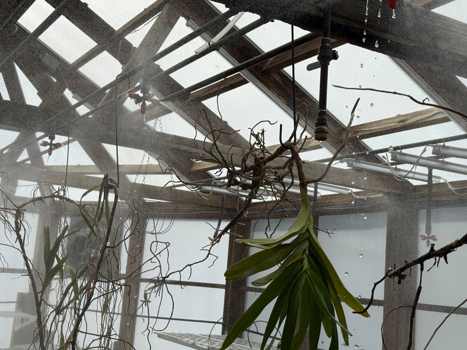
| Overhead trusses | 2×4 treated, double top plate | 72” (6’) on center |
| Top plate height | 96” (8’ 0”) — exterior framing is 92”, plus double 2×4 top plate = 96” to bottom of truss | — |
| Ridge beam | ~12” thick, runs full N-S length | Continuous |
| Truss-to-ridge rise | 35” from bottom of horizontal truss to bottom of ridge beam | — |
| Polycarbonate panels | 6mm twin-wall, spans between trusses | Roof + all walls above pony wall |
Glazing
All primary greenhouse glazing surfaces are Gallina PoliCarb 2P — 6mm twin-wall polycarbonate with an opal (frosted) finish, installed December 2023. The patio door includes a removable glass insert, but the growing envelope is polycarbonate. The opal finish diffuses incoming light, so plants receive softened light rather than a clean direct beam.
Doors
| Door | Location | Type | Seasonal Use |
|---|---|---|---|
| House door | North wall | Interior → bar/sunroom | Always closed. Passive thermal buffer. House heat leaks in (~68°F floor overnight). |
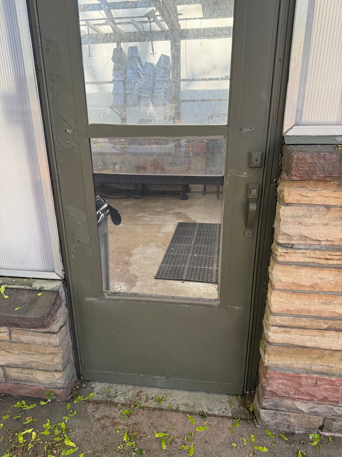
| Patio door | East wall, NE corner | Glass + screen combo | Winter: glass insert for insulation. Summer: glass removed → screen or fully open for ventilation. |
| The patio door is the single most important manual climate variable. Open = cooling (cross-ventilation) but humidity loss. Closed = humidity retention but temps climb. |
Orientation & Solar Geometry
The greenhouse is not aligned to perfect north-south. Its long axis runs at a measured heading of 156.49°, which is roughly NNW to SSE, with the west side facing WSW and the east side facing ENE. That matters for how solar load actually arrives:
- morning light enters from the ENE side but is heavily modified by the east-side tree
- the WSW-facing wall takes late-day heat harder than a due-west simplification would suggest
- the faceted south end spreads midday solar across multiple faces instead of one flat wall
- future sun-angle, shade-cloth, and seasonal transmission analysis should use this 156.49° rotated geometry, not a perfect cardinal assumption
These constants are the export baseline for public diagrams, simulation notes, and future structure data files: interior usable area, air volume, long-axis heading, wall lengths, polycarbonate envelope, and altitude should stay consistent across pages.
Surroundings
| Feature | Location | Impact |
|---|---|---|
| House | Northwest | Connected via north wall. Thermal buffer ~68°F overnight. |
| Large tree | East side | Shades east + SE walls in morning. Sensor blind spot until ~10:18 AM. |
Thermal Envelope
| Metric | Value | Notes |
|---|---|---|
| Glazed surface area | ~785–810 sq ft | Walls above pony wall + roof. Corrected estimate. |
| Heat loss rate | ~480–495 BTU/hr per °F delta | U-value 0.61 × ~800 sq ft × ΔT |
| Peak solar heat gain | ~87,000 BTU/hr | Realistic peak assuming ~400 sq ft of effective receiving area at 330 BTU/hr/sq ft × SHGC 0.66 |
| Fan cooling capacity | Variable by ΔT | ~15,900 BTU/hr at 3°F ΔT, ~52,900 BTU/hr at 10°F ΔT (requires 4,900 CFM) |
| Fog cooling capacity | ~5,600 BTU/hr | 1,644W evaporative cooling, minus motor heat |
| Air exchange time | 44 seconds | 4,900 CFM through 3,614 cu ft |
| Cooling deficit at peak | Structural | Fans cannot cool below ambient. Equilibrium will always be higher than outdoor peak. |
| Overnight retention | 5–8°F above outdoor without heaters | Concrete slab + house heat + poly insulation |
Glazed Area Breakdown
| Surface | Dimensions | Area |
|---|---|---|
| East wall (above pony wall) | 269” × 70.5” | ~131.6 sq ft |
| West wall (above pony wall) | 269” × 70.5” | ~131.6 sq ft |
| SW face (above pony wall) | 82.25” × 70.5” | ~40.2 sq ft |
| SE face (above pony wall) | 82.25” × 70.5” | ~40.2 sq ft |
| South center face (above pony wall) | 85” × 70.5” | ~41.5 sq ft |
| North gable triangle | ~0.5 × 164” × 47” | ~26.7 sq ft |
| South gable triangle | ~0.5 × 85” × 47” | ~13.9 sq ft |
| Roof (two main slopes + south taper) | ~310” avg length × ~89” slope each | ~350–370 sq ft |
| Total glazed | ~776–796 sq ft | |
| The north wall below the gable is shared with the house and is not glazed. Wall height above the 25.5” pony wall is 70.5”. Roof slope calculated as √((76”)² + (47”)²) ≈ 89.4” per side (accounting for 12” ridge beam width). | ||
| The defining tension: The greenhouse has a high glazing-to-floor ratio (roughly 2.1:1). The opal polycarbonate diffuses light beautifully, but it still admits a very large solar heat load relative to the usable growing area. | ||
| This makes the structure a sun trap in summer. Cooling is not fundamentally limited by raw fan nameplate capacity, it is limited by the combination of massive solar load, dry intake air, altitude-reduced air density, and the fact that ventilation cannot cool below ambient. The highest-leverage physical intervention is still external shade on the roof and WSW wall. |
Live Light Transmission
The hexagonal shape creates a daily signature — transmission peaks when the southwest face catches afternoon sun, and drops when the east tree blocks morning light.
Floor
The concrete slab is a thermal battery. South zone stays 2–4°F warmer overnight from stored solar heat. On moderate nights (50°F+ outdoor), the slab’s retained heat plus poly insulation plus house connection mean the greenhouse holds above 67°F without any heater assistance.
Interior Equipment Layout
North Wall (Equipment Zone)
No planting. The 49” shelf spans the full width as an equipment staging surface.
- House door: west side of wall, standard interior door, always closed
- Stainless steel sink: centered on wall, with faucet
- Irrigation/sprinkler manifold: mounted above sink — horizontal header pipe with 8 vertical drops and 4 solenoid valves controlling clean and fertigation water paths to south, west, and center zones
- ESP32 controller: Kincony KC868-E16P (ESPHome firmware), west side, mid-height
- Four SSR relay boxes: CG SSR-25DA (DC→AC, 25A), spaced along wall near ceiling
- Intake vent: 24×24” (4 sq ft opening), mechanical actuator with insect screen, centered horizontally, mounted high near roofline. Controlled by ESP32 economizer logic — opens when outdoor enthalpy is lower than indoor.
- Copper irrigation piping: runs from manifold to distribution points throughout greenhouse
East Wall
- Patio door: 33” wide glass/screen combo, starts 32” from NE corner
- Wire shelving: between patio door and workbench (seedling trays, propagation flats)
- Workbench: south of patio door area, marks boundary before hydro begins
- Hydroponic NFT system: 3× 4” PVC rails (A, B, C), each with top and bottom row, 60 total positions. Grodan rockwool in net cups with clay pellets. General Hydroponics Flora/Bloom/Grow nutrients. Recirculating pump.
- Hydro reservoir tank: floor level below rails, near north end of hydro run
- 14× Barrina 2FT LED grow lights: mounted above hydro at ~12” on-center spacing
West Wall
- 6 shelf bays: evenly spaced along full 22’5” wall, each with top tier (~4.5’) and bottom tier (~2.5’), wire shelving uprights
- 15× Barrina 2FT LED grow lights (24W each, CRI 80): shelf-level, ~2–3 per bay
- 15× Barrina 4FT LED grow lights (42W each, CRI 98): mounted on rafters overhead at 36” on-center spacing
- 3 overhead mister heads: evenly spaced along wall
Southwest Face
- 1× KEN BROWN 18” shutter exhaust fan (2,450 CFM, 52W): high-mounted
- 2 shelf bays (top and bottom tiers), angled to match wall face
Southeast Face
- 1× KEN BROWN 18” shutter exhaust fan (2,450 CFM, 52W): high-mounted
- 2 shelf bays (top and bottom tiers), angled to match wall face
South Center Face (End Cap)
- Narrow face between the two exhaust fan walls
- Wall-mounted mister nozzles (part of south zone’s 6 heads / 30 nozzles)
South Zone Floor
- Floor pots centered in hex taper (established canna lilies)
Ceiling-Hung Equipment
Both major HVAC units are suspended from the trusses, not floor-standing or wall-mounted. They occupy the vertical band between the truss bottom (96”) and approximately 18” below it — the same zone where the 4FT overhead grow lights and relay boxes live.
- Lennox LF24-75A-5 gas furnace (75,000 BTU): ceiling-hung from trusses via metal straps, approximately 6’ from north wall, with flue pipe rising through roof
- AquaFog XE 2000 HumidiFan (1,644W): ceiling-hung from trusses via metal straps, approximately 5’ from north wall, output nozzle oriented to blow N→S along the greenhouse long axis
Mister Distribution
| Zone | Active Heads | Active Nozzles | Mount Type | Avg VPD Drop/Pulse |
|---|---|---|---|---|
| South | 6 | 30 | Wall-mounted, 2 rows on south faces | 0.15 kPa |
| West | 3 | 15 | Overhead | 0.13 kPa |
| Center | 5 | 25 | Overhead | Active but underperforming (0.04 kPa avg). Center drip is disconnected; misters are operational. |
| Nozzle spec: Micro Drip 360° emitters, 1/2”, 1–5 Bar, 0–2M radius, 0–300 L/H adjustable. Only one zone runs at a time — water pressure is insufficient for simultaneous zones. The firmware rotates based on which zone has the highest VPD. | ||||
| Flow rate: ~1 GPM per zone, ~1–2 gallons per 45–60 second pulse. Warm water supply (86°F from Rinnai RE140iN tankless heater) for better evaporation. |
Sensor Placement
| Sensor | Zone | Position | Notes |
|---|---|---|---|
| Tzone SHT3X (Modbus 2) | North | 4’ height, center of north wall | Reads equipment zone, not growing conditions |
| Tzone SHT3X (Modbus 3) | West | 4’ height, center of west wall | Representative of west shelf microclimate |
| Tzone SHT3X (Modbus 4) | South | 4’ height, south zone | Hottest reading at solar noon |
| Tzone SHT3X (Modbus 5) | East | 4’ height, south half of east wall | Tree shade delays morning readings until ~10:18 AM |
| CO₂ (Kincony analog) | North | Near north probe | Greenhouse-average, not zone-specific |
| Lux (LDR) | North | Near north probe | Saturates at ~28K lux. Not reliable for high-light measurement. |
| Soil (SEN0601) | South | Buried, floor zone | Moisture + temp + EC |
| Soil (SEN0600) | East | Buried, floor zone | Moisture + temp |
| Soil (SEN0600) | West | Buried, floor zone | Moisture + temp |
| Camera 1 | North | Ceiling-mounted, NW area | Model and security details withheld |
| Camera 2 | South | Ceiling-mounted, south zone | Model and security details withheld |
| Flow meter (DAE) | North | Inline on supply | Tracks water consumption |
| YINMIK WiFi | East | Hydro reservoir | pH, EC, TDS, ORP, water temperature |
| Shelly EM50 | North | Panel | 3-circuit energy monitor |
| All Tzone probes are in louvered housings, mounted center of their associated wall at 4 feet off ground. They are not specifically shielded from mist (may affect RH readings during misting events). |
Vertical Zone Map
| Band | Height | Contents |
|---|---|---|
| Floor to pony wall | 0–25.5” | Concrete slab, stone pony wall, floor pots, soil probes, hydro reservoir |
| Pony wall to bottom shelf | 25.5”–30” | Polycarbonate starts, lower shelf supports |
| Bottom shelf tier | ~30” | West/south/east bottom shelf bays |
| Mid-wall (growing zone) | 30”–54” | Upper growing zone, top shelf tier (~54”), north wall 49” shelf |
| Sensor band | ~48”–60” | Climate probes at 4’ height |
| Upper wall | 54”–96” | Polycarbonate panels, wall studs, patio door head, intake vent (high) |
| Truss zone to peak | 96”–143” | Trusses (6’ OC), ceiling-hung furnace + fog machine, 4FT grow lights, relay boxes, ridge beam |
| The 96”–143” band is the most congested vertical zone. Furnace, fog machine, grow lights, and relay boxes all share it with the structural trusses. |
Annotated Floor Plan
ESP32 controller, four relay boxes, stainless sink, irrigation manifold, house door, and 24"×24" intake vent.
Six shelf bays, 15× 4FT overhead lights, 15× 2FT shelf lights, and three mister heads.
Patio door, propagation shelves, workbench, NFT rails A/B/C, 60 hydro positions, reservoir, and 14× 2FT lights.
Two 2,450 CFM exhaust fans on angled faces, south mister nozzles, canna lilies on the floor, and the highest solar load.
Where to Go Next
- Equipment — relay maps, sensors, and controller hardware
- All Zones — climate profiles and planting for each zone
- Climate at 5,000 Feet — how altitude and arid air shape the control problem
This physical envelope is why the climate control problem is what it is.